There are five Types of Circuit Breakers and In this article we will speak about
- Air break circuit breaker
- Air-Blast Circuit-Breaker
- Bulk Oil and Minimum Oil Circuit Breaker
- Sulphur Hexafluoride (SF6) Circuit Breaker and SF6 Insulated Metalclad switchgear
- Vacuum circuit breaker
Bulk Oil and Minimum Oil Circuit Breaker
Such circuit breakers utilize dielectric oil (transformer oil) for arc extinction.
- In bulk oil circuit breakers, the contacts are separated inside a steel filled with dielectric oil.
- In minimum oil circuit breakers, the contacts are separated in an insulation housing (interrupter)filled with dielectric oil.
The oil in oil circuit breakers ( OCBs) serves two purpose. It insulates between the phases and between the phases and the ground, and it provides the medium for the extinguishing of the arc. When electric arc is drawn under oil, the arc vaporizes the oil and creates a large bubble that surround the arc. The gas inside the bubble is around 80% hydrogen, which impairs ionization. The decomposition of oil into gas requires energy that comes from the heat generated by the arc. The oil surrounding the bubble conducts the heat away from the arc and thus also contributes to deionization of the arc.
Main disadvantage of the oil circuit breakers is the flammability of the oil, and the maintenance necessary to keep the oil in good condition ) i.e. changing and purifying the oil).
Bulk oil circuit breaker (tank type circuit breakers) are becoming obsolete and have been described here in brief.
Minimum oil circuit breaker has the following demerits:
- Short contact life.
- frequent maintenance.
- Possibility of explosion.
- Larger arcing time for small current.
- Prone to re-strike
- They are being superseded by SF6 circuit breakers in all ranges.
1 Tank type or Bulk Oil Circuit Breaker (now obsolete)
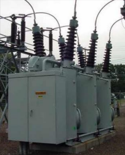
Bulk oil circuit breakers are enclosed in metal-grounded weatherproof tanks that are referred to as dead tanks. The tank type circuit breakers had 3 separate tanks for 72.5 KV and above (Fig. 12a). For 36 KV and below, single tank construction, phase barriers were provided between phase.
The contact separation takes place in steel tanks filled with oil. The gases formed, due to the heat of the arc, expand and set the turbulent flow in the oil. The arc was drawn directly inside of the container tank without any additional arc extinguishing but the one provided by the gas bubble surrounding the arc. Plain break breakers were superseded by arc controlled oil breakers.
To assist arc extinction process, arc control devices were fitted to the contact assembly. These were semi-enclosed chamber of dielectric materials. The purpose of the arc control devices is to improve operating capacity, speed up the extinction of arc, and decrease pressure on the tank. The performance of oil circuit breaker depended on the effectiveness of the arc control devices.
These are two types of such breakers:
- Self blast oil circuit breakers - in which arc control is provided by internal means i.e. are itself facilitates its own extinction efficiency.
- Forced blast oil circuit breakers - in which arc control is provided by mechanical means external to the circuit breaker.
Self blast oil circuit breaker –
in this type of breakers, the gases produced during arching are confined to a small volume by the use of an insulating rigid pressure chamber or explosion pot surrounding the contacts. The space available for the arc gases is restricted by the chamber so a very high pressure is developed to force the oil and gas through or around the arc to extinguish it. The magnitude of the pressure depends upon the value of fault current to be interrupted. The arc itself generates the pressure so such breakers are also called self generated pressure oil circuit breakers.
The pressure chamber is relatively cheap and gives reduced final arc extinction gap length and arcing time as against the plain oil breaker.
Different types of explosion pots are described below:
Plain explosion pot -
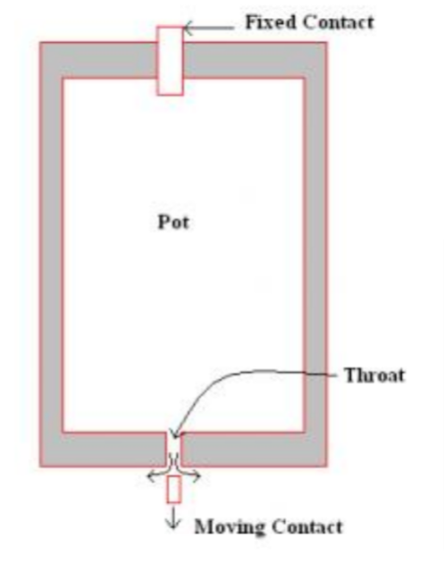
It is a rigid cylinder of insulating material and encloses the fixed and moving contacts as shown in Fig. 13. The moving contact is a cylindrical rod passing through a restricted opening called throat at the bottom. When fault occurs the contacts get separated and arc is struck between them. The heat of the arc decomposes oil into a gas at very high pressure in the pot. This high pressure forces the oil and gas
 |
| Figure .13 Plain explosion pot principle |
If the arc extinction will not take place when the moving contact is still within the pot, it occurs immediately after the moving contact leaves the pot. It is because, emergence of moving contact will be followed by violent rush of gas and oil through the throat production rapid extinction.
Limitation of this type of pot is that it cannot be used for very low or very high fault currents. With low fault currents the pressure developed is small, thereby increasing the arcing time. And with high fault currents, the gas is produced so rapidly that the plot may burst due to high pressure. So this pot is used on moderate short circuit currents only
Cross jet explosion pot -
Figure 14 shows the cross jet pot which is made of insulating material and has channels on one side that acts as arc splitters. The arc splitter help in increasing the arc length, thus facilitating arc extinction. when fault occurs, the moving contact of the circuit breaker begins to separate and arc is struck in the top of the pot. The gas generated by the arc exerts pressure on the oil in the back passage. When the moving contact uncovers the arc splitter ducts, fresh oil is forced across the arc path. The arc is therefore driven sideways into the arc splitters, which increase the arc length, causing arc extinction.
The cross jet explosion pot is used for interrupting heavy fault currents. For low fault currents the gas pressure is small and consequently the pot does not give a satisfactory operation.
figure 14 Principle of cross jet explosion pot |
Self compensated explosion pot -
This pot is a combination of plain explosion pot and cross jet explosion pot. So it can interrupt low as well as heavy short circuit currents. Figure 15 shows the itself compensated explosion pot.
Forced Blast Oil Circuit Breaker
In this type of circuit breaker there is a piston attached to a moving contact. When fault occurs the moving contact moves and hence the piston associated with it also moves producing pressure inside the oil chamber. So the oil gets movement or turbulates and quenching the arc.
The arc control devices can be classified into two groups: cross-blast and axial blast interrupters (Fig. 16).
Figure contents:
- Fixed contact assembly
- Arc
- Moving contact with tungsten copper tip
- Fiber reinforced tube
- Gas evolved by decomposition of oil
- Dielectric oil
- Outer enclosure (Porcelain or Fiber Reinforced Epoxy )
In cross blast interrupters, the arc is drawn in front several lateral vents. The gas formed by the arc causes high pressure inside the arc control device. The arc is forced into the lateral vents in the pot, which increases the length of the arc and shortens the interruption time. The axial blast interrupters use similar principle as the cross blast interrupters. However, the axial design has a better dispersion of the gas from the interrupter.
Figure 17 illustrates a typical 69 KV breaker of 2500 MVA breaking capacity. All three phases are installed in the same tank. The tank is made of steel and is grounded. This type of breaker arrangement is called the dead tank construction. The moving contact of each phase of the circuit breaker is mounted on a lift rod of insulating material. There are two breaks per phase during the breaker opening. The arc control pots are fitted over the fixed contacts. Resistors parallel to the breaker contacts may be installed alongside the arc control pots. It is customary and convenient for this type of breakers to mount current transformers in the breaker bushings.
| Fig. 17 dead tank oil circuit breaker |
Figure contents :
- bushing
- oil level indicator
- vent
- current transformer
- dashpot 6 plunger guide
- arc control device
- resistor
- plunger bar
The practical limit for the bulk oil breakers is 275 KV. Figure 18 shows 220 KV one phase dead tank circuit breaker.
| Figure 18 Single phase tank oil circuit breaker |
Figure content ;
- bushing
- oil level indicator
- vent
- linear linkage
- dashpot
- guide block
- arc control unit
- parallel contact
- resistor
- plunger bar
- impulse cushion
The oil circuit breakers are usually installed on concrete foundations at the ground level. During interruption of heavy fault currents the breakers tend to move. To minimize the damage to the breakers, breakers with very high interrupting capacity have an impulse cushion is provided at the bottom of the breakers. The cushion filled with an inert gas, for example nitrogen.
Figure 19 illustrates the tank type oil circuit breaker, in open position, with the arc is not yet extinguished
Figure 19 Schematic diagram of bulk oil circuit breaker |
The major disadvantages of tank type C.B. are ;
- Large quantity of oil is necessary in oil circuit breakers though only a small quantity is necessary for arc extinction.
- The entire oil in the tank is likely to get deteriorated due to sludge formation in proximity of the arc. Then the entire oil needs replacement.
- The tanks are too big, at 36 KV and above, and the tank type oil circuit breaker loses its simplicity,
The above causes led to the development of minimum oil circuit breakers. As the name itself signifies, the minimum oil circuit breaker requires less oil. The arc extinction medium is dielectric oil, the same as that used in tank type circuit breakers. There is no steel tank but the arc extinction takes place in a porcelain containers.


